
November 2001
|
|
Fitting instructions
Halda Speed Pilot can be fitted to all existing makes of cars, commercial vehicles and buses. The fitting frame supplied makes the installation a simple job, this frame is usually screwed to the underside of the dashboard in a position where the Speed Pilot can be seen by the driver at a glance.
The most suitable position will naturally vary with different cars, it can be on one side or other of the steering column but if it can be placed between, the driver and the front passenger, this will enable the latter to see the Pilot also.
The Pilot is fastened into the fitting frame by means of the metal straps and the frame can be bent to a certain extent to give the Pilot the most suitable angle when fitted. Some car owners may prefer to fit the Pilot into the dashboard panel. In this case an aperture 3" X 5" (75 mm X 125 mm) must be made, the Pilot is fitted into this and fastened by means of the metal straps.
On some cars fitted with floor type gear levers and with little leg room, lack of space may not allow of fitting between driver and passenger and so dashboard fitting may sometimes be essential.
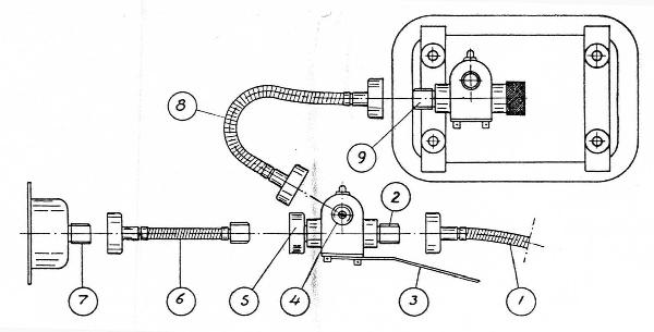
Attachment of Speed Pilot
Electric connection
Since some cars have 6 and others 12 volt system, lamps are not supplied with Speed Pilot. The correct lamp should be fitted and the lamp contact connected to the switch controlling the Dashboard light.
Adjustment
The Speed Pilot is driven from the speedometer drive. The number of revolutions of the speedometer drive to the mile or kilometer varies with different makes of car.
The gearing of the Speed Pilot must be adjusted therefore in accordance with the speedometer revs in each case.
The required adjustment can be carried out very quickly by means of the adjustment screw fitted on the underside of the Speed Pilot.
Each Pilot is adjusted on delivery to the equivalent of 900 revs of the speedometer to one mile or 576 revs per kilometer.
Do not disturb the adjustment screw before you have ascertained the speedometer revs of the car to which it will be fitted. This information is usually given on the face of the speedometer.
If the actual speedo revs of the car are 576 per km or 900 per mile, then the Speed Pilot is correctly adjusted, and thus it will not be necessary to touch the adjustment screw.
Should the speedo drive revs be more than 576 per km or 900 per mile, then the adjustment screw must be moved a certain number of turns on the adjustment scale to minus ( - ). If the speedometer revs should be less, then the adjustment screw must be moved a certain number of turns towards plus ( + ).
The number of turns of the adjustment screw required is given in the following table, this covers the speedo revs most commonly met with both for miles and kilometers.
| MILES | KILOMETERS | ||
| Speedo Revs per mile | Number of turns on adjustment screw | Speedo Revs per kilometer | Number of turns on adjustment screw |
| 546 | 64,8 towards + | 510 | 13 towards + |
| 642 | 40,2 towards + | 550 | 4.7 towards + |
| 800 | 12,5 towards + | 560 | 3 towards + |
| 900 | correct | 565 | 2 towards + |
| 980 | 8,2 towards - | 576 | correct |
| 1000 | 10 towards - | 585 | 1,5 towards - |
| 1012 | 11,1 towards - | 590 | 2,4 towards - |
| 1040 | 13,5 towards - | 595 | 3,2 towards - |
| 1100 | 18,2 towards - | 600 | 4 towards - |
| 1140 | 21 towards - | 601.34 | 4,2 towards - |
| 1180 | 23,7 towards - | 605 | 4,8 towards - |
| 1300 | 30,8 towards - | 610 | 5,6 towards - |
| 1325 | 32 towards - | 615 | 6,3 towards - |
| 1375 | 34,5 towards - | 620 | 7,1 towards - |
| 1400 | 35,7 towards - | 625 | 7,8 towards - |
| 1425 | 36,8 towards - | 630 | 8,6 towards - |
| 1475 | 39 towards - | 632,5 | 8,9 towards - |
| 1500 | 40 towards - | 633 | 9 towards - |
| 1525 | 41 towards - | 635 | 9,3 towards - |
| 1550 | 41,9 towards - | 640 | 10 towards - |
| 1575 | 42,9 towards - | 645 | 10,7 towards - |
| 1600 | 43,7 towards - | 650 | 11,4 towards - |
| 1650 | 45,4 towards - | 655 | 12,1 towards - |
| 1675 | 46,3 towards - | 658 | 12,5 towards - |
| 720 | 20 towards - | ||
| 747 | 22,9 towards - | ||
| 795 | 27,5 towards - | ||
| 820 | 29,8 towards - | ||
| 840 | 31,4 towards - | ||
| 845 | 31,8 towards - | ||
| 870 | 33,8 towards - | ||
| 895 | 35,6 towards - | ||
| 900 | 36 towards - | ||
| 920 | 37,4 towards - | ||
| 940 | 38,7 towards - | ||
| 1000 | 42,4 towards - | ||
| 1020 | 43,5 towards - | ||
| 1030 | 44,1 towards - | ||
| 1040 | 44,6 towards - | ||
| 1050 | 45,1 towards - | ||
| 1055 | 45,4 towards - | ||
| 1080 | 46,7 towards - | ||
| 1090 | 47,2 towards - | ||
| 1240 | 53,5 towards - | ||
After adjustment in accordance with the table, the SpeedPilot is theoretically correct. In practice however, the accuracy depends on a number of other factors also, for instance that tyre size and tyre pressures are correct, or even that the speedometer works within reasonable tolerance of the revs per mile or km indicated.
It is therefore desirable to check that the Speed Pilot's correct in operation, it can be adjusted to 99.5 % exactness.
The best check is to test against a measured road distance, but check can also be made against the mileage register of the speedometer. In the latter case the degree of accuracy cannot of course greater than that of the speedometer.
For normal purposes this is quite sufficient, but for competition use or any other case where extreme accuracy is required, check should be made against a measured road distance.
For final correction the adjustment screw is again used, procedure being as follows:
If the trip counter of the Pilot shows more than the measured road distance then the adjustment screw must be turned towards minus ( - ).
If the trip counter of the Pilot shows less than the measured road distance then the adjustment screw must be turned towards plus ( + ).
It is suggested that the customer should be shown the adjustment screw and given instructions for correcting his Speed Pilot.
Most customers are bound to appreciate knowing something about their Speed Pilot and particularly how to adjust it for the greatest possible accuracy.
To make the final adjustment after road test to bring the Speed Pilot to an accuracy of 99.5% the following simple formulas should be used. They will enable you to work out exactly how much the adjustment screw has to be turned and they are the same for both miles and kilometers.
The number of turns of the adjustment screw required we call "N". The distance shown on the Pilot trip meter we call "T". The distance shown on the speedometer or the measured road distance we call "D".
P. S.We give two typical cases that can occur and they are worked out as follows.
Pilot trip meter shows MORE than the actual distance.
The screw must be turned towards minus (-)N = 100 - (T-D) TExample: Actual distance D = 3 miles.
Trip meter shows T = 3.1 miles.
Substituting these figures in the formula givesN = 100 - (3.1 - 3) = 100 - 0.1 = 10.0 = 3.23 3.1 3.1 3.1The screw must thus be moved 3.23 turns towards minus (-).
Pilot trip meter shows LESS than the actual distance.
The screw must be turned towards (+)N = 100 - (D -T) TExample: Actual distance D = 3 miles.
Trip meter shows T = 2.9 miles.
Substituting these figures in the formula givesN = 100 - (3 - 2.9) = 100 - 0.1 = 10.0 = 3.45 2.9 2.9 2.9The screw must thus be moved 3.45 turns towards plus (+).
Formula for Primary Adjustment
For those cases where the figure for Speedometer revs is one which does not appear in the table given above, the required number of turns of the adjustment screw can be worked out by means of the formulas given below.
If we call the number of turns required "N" and the actual speedometer revs "R" then we have the following formulas for miles and kilometers respectively.
Formula for Miles
N = 100 -  90.000
             R
N = 90.000 - 100
      R
Example of 1) above:
R proves to be 1.000 revs per mile.
N = 100 - 90.000
           1.000

Worked out this becomes
N = 100 - 90; N = 10

The adjustment screw must thus be moved 10 turns towards minus ( - ).
Example of 2) above:
N = 90.000 - 100
      750

Worked out this becomes
N = 120 - 100;  N = 20

The adjustment screw must thus be moved 20 turns towards plus ( + ).
Formula for Kilometers
N = 100 - 57.600
            R
N = 57.600 - 100
      R
Example of 1) above:
R proves to be 640 revs per kilometer
N = 100 - 57.600
           640

Worked out this becomes
N = 100 - 90;  N = 10

The adjustment screw must thus be moved 10 turns towards minus ( - ).
Example of 2) above:
R proves to be 522 revs per Km.
N = 57.600 = 100
     522

Worked out this becomes
N = 110,3 - 100; N = 10,3

The adjustment screw must thus be moved 10,3 turns towards plus ( + ).
Scotchlite label
A red label made of self reflecting scotchlite and with the word "SPEEDPILOT" printed on it, is supplied with each instrument. Stick this label to the back of the car.
HALDEX AB HALMSTAD SWEDEN
(Transcribed by Bill Jonesi)