
November 2001
|
|
Instructions for using the Speedpilot Mk. IV
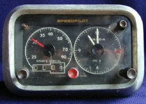 Speedpilot Mk. IV Sports Special |
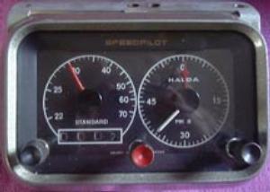 Speedpilot Mk. IV Standard |
| SPORTS SPECIAL: | |
| Catalogue No. | Average speed range |
| 365038 | 25-90 (12.5-45) miles/hour |
| 365009 | 40-150 (20-75) km/hour |
| STANDARD: | |
| Catalogue No. | Average speed range |
| 365014 | 22-75 miles/hour |
| 365015 | 35-120 km/hour |
| T-gear Catalogue No. |
Connection to Speedo and Size of squared end of cable |
Extension Transmission | |
| Length 150 mm. (6") Cat. No. |
Length 300 mm. (12") Cat. No. |
||
| V-11 | NF 5/8" X 18 (2.7 X 2.7 mm) | T-11 | T-113 |
| V-12 | M 12 X 1 (3 X 3 mm) | T-12 | T-123 |
| V-13 | M 16 X l (2.7 X 2.7 mm) | T-13 | T-133 |
| V-14 | M 18 X 1.5 (2.7 X 2.7 mm) | T-14 | T-143 |
| V-15 | NF 1 1/4" X 20 (3.5 X 3.5 mm) | T-15 | T-153 |
| V-16 | M 12 X 1 (2.7 X 2.7 mm) | T-16 | T-163 |
| Catalogue No.: | PT-312 | PT-468 | PT-624 | PT-832 |
| Length: | 300 mm (12") | 450 mm (18") | 600 mm (24") | 800 mm (32") |
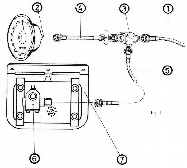
FITTING INSTRUCTION:
Speedometer cable (1) is detached from speedometer head (2) and is screwed to T-gear (3). The T-gear is then coupled to the speedometer head, either directly or, where space does not permit this, by means of an extension transmission (4).
The transmission cable (5) is then coupled between the T-gear (3) and the gear box (6) on the back of the Speed Pilot (7). All cables should lie in as straight as possible and they should be checked by hand to ensure that they rotate freely.
Speed Pilot can be fitted to any make of car. The simplest method of installation is by screwing the fitting frame Supplied in a suitable place on the underside of the dashboard panel. When fitted into the dashboard panel the Speed Pilot is fastened by means of the two metal straps supplied with each instrument.
|
|
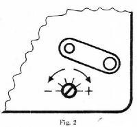
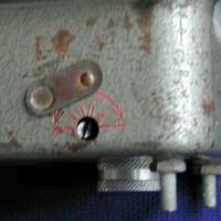
| Adjustment screw is in at an angle. |
ADJUSTMENT:
On the underside of the Pilot there is an adjustment screw (see fig. 2), by which the required adjustment can be carried out. Each Pilot is adjusted on delivery to the equivalent of 900 revs of the speedometer to one mile or 576 revs per kilometer.
With the aid of the following simple formulas you will be able to work out exactly how much the adjustment screw has to be turned for the final adjustment. They are the same for both miles and kilometers.
The number of turns of the adjustment screw required we call "N". The distance shown on the Pilot trip meter we call "T". The measured road distance we call "D".
Examples are given of working out two typical cases where adjustment is required.
Pilot trip meter shows MORE than the actual distance.
The screw must be turned towards minus (-)
N = 100 - (T-D)
         T
Example: Actual distance D = 3 miles.
Trip meter shows T = 3.1 miles.
Substituting these figures in the formula gives
N = 100 - (3.1 - 3) = 100 - 0.1 = 10.0 = 3.23
          3.1            3.1       3.1
The screw must thus be moved 3.23 turns towards minus (-).
Pilot trip meter shows LESS than the actual distance.
The screw must be turned towards (+)
N = 100 - (D -T)
          T
Example: Actual distance D = 3 miles.
Trip meter shows T = 2.9 miles.
Substituting these figures in the formula gives
N = 100 - (3 - 2.9) = 100 - 0.1 = 10.0 = 3.45
         2.9             2.9       2.9
The screw must thus be moved 3.45 turns towards plus (+).
1n addition a special knob is provided on the front of the Sports Special model which allows for correction of about + 8%.
The clock is regulated by means of a screw located on the back of the Pilot.
|
|
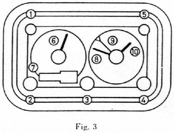
You now pilot drive. As long as you keep the average speed set, the pilot hand and the minute hand will synchronize - exactly, if you are on schedule. If not, the hands will separate and will show directly in minutes (and parts of minutes) how much ahead or behind the required time you are! You only have to accommodate your speed to the Speed Pilot.
(Transcribed by Bill Jonesi)